
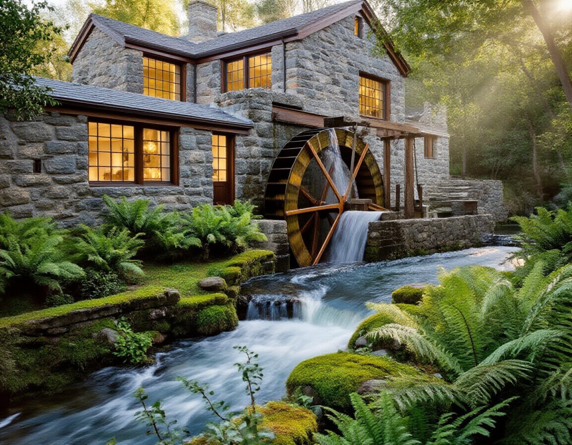
To rebuild a Historic Water Mill, is usually a once in a lifetime project. You start by defining what you’ll produce—flour, power, or demonstration runs—because that choice drives every design decision. You then test feasibility: confirm water rights, check access for lifting gear, map flood and scour risks, and note ecological constraints. You survey the masonry, timbers, wheelpit, and drivetrain, and you measure head and seasonal flow to size gates and machinery. Once you see what’s failing first, you’ll have to decide whether to…
Key Takeaways
- Define the mill’s intended use and performance targets, including duty cycle, rpm band, power output, and transmission method.
- Reconstruct the historic layout and process flow using archival records, measured surveys, and wear patterns to keep operation authentic.
- Confirm water rights, access, and permitting early, including abstraction limits, hands-off flows, heritage consents, and flood or habitat constraints.
- Assess structural and machinery condition, inspecting foundations, masonry, timber, gates, wheel/turbine, shafts, bearings, gearing, leakage, and siltation.
- Measure head and seasonal flow reliably, building a flow-duration curve and net-head calculation to size equipment and plan bypass and residual flows.
Decide What You’ll Use the Mill For
Before you touch the headrace, wheel, or generator, decide what the mill must deliver—mechanical work, electrical power, food processing, demonstration milling, or a mixed-use output—because that choice sets every downstream design constraint. Define duty cycle, target torque or kW, rpm band, and acceptable efficiency, then map loads to transmission: belts, gears, line shafts, or direct-drive alternators. If you’ll mill grain, specify throughput, particle size, sanitation boundaries, and material choices; if you’ll run shop tools, specify peak starting loads and clutching. For interpretive operation, prioritize visibility, guarding, and controllable speed. Mixed-use needs switching logic and decoupling so one load won’t stall another. Tie requirements to Creative funding milestones and Community engagement outcomes so sponsors back a measurable, operable scope.
Check Feasibility: Water, Access, Risks, Constraints
Before you commit to upgrades, you’ll verify water flow rights and quantify usable head and seasonal discharge against your target output. You’ll map site access from road to wheelpit, then rate hazards like unstable banks, confined spaces, overhead loads, and flood-stage egress paths. You’ll document constraints—easements, permitting triggers, protected habitats, and setback requirements—so your design aligns with legal, safety, and constructability limits.
Assess Water Flow Rights
Although the headrace, weir, and tailrace may still look intact, you can’t assume you’re entitled to divert or impound water at historic rates, so start by verifying the site’s water rights and operating constraints in writing. Pull deeds, easements, prior decrees, and any riparian or appropriative filings, then confirm the authorized season, max diversion rate, storage volume, and return-flow obligations. Check whether the right is appurtenant to the parcel and whether nonuse triggered forfeiture or abandonment. Request agency correspondence on minimum bypass flow, fish passage, and water-quality standards, and map these to design operating points. Document measurement methods (staff gauge, weir equation, ultrasonic meter) that prove compliance during commissioning. If rights are shared, define priority and curtailment triggers in an operations plan.
Evaluate Site Access Hazards
Once you’ve pinned down what water you can legally move and when, walk the site like you’re planning a build: identify how people, equipment, and materials will actually reach the weir, headrace, mill structure, and tailrace without creating unacceptable risk. Map slopes, soft ground, and overhead obstructions; verify turning radii, crane setup pads, and laydown areas. Flag confined spaces, unstable masonry, and slip/trip zones at algae-coated aprons and wet stones. Assess flood stage access: locate high-ground routes and emergency egress.
Check Water quality where disturbance could mobilize sediment, oils, or legacy contaminants; plan containment and dewatering points. Specify barriers, handrails, anti-slip surfacing, and fall protection anchors. Install safety signage at pinch points, energized equipment, and public interfaces.
Research the Mill’s History and Original Layout
To restore a historic water mill without losing performance or authenticity, you’ll need to reconstruct its original operating logic from evidence, not assumptions. Start with archival deeds, insurance maps, estate accounts, and millwright invoices to establish dates, ownership, and intended products, tying choices to Historical significance and Cultural preservation. Extract dimensions from photographs by scaling known elements (brick courses, door widths), then draft a measured hypothesis plan.
Next, map the process flow: intake to headrace, control gates, wheel/runner placement, mainshaft line, gearing ratios, stone or saw frame alignment, and discharge routing. Cross-check wear-pattern narratives in records against period millwright standards. Build a component genealogy, noting replacements by era, so your design reinstates correct power transmission paths and operational sequencing.
Survey the Site, Structure, and Machinery Condition
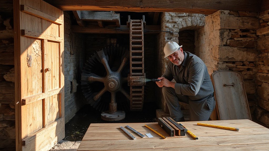
Start with a structural integrity survey: you’ll verify foundation bearing, wall plumbness, timber section loss, and connection performance, then flag any movement with crack gauges and level runs. Next, inspect the waterpower train—headrace, gates, penstock or flume, wheel/turbine, shafts, bearings, and gearing—checking alignment, wear, corrosion, and leakage under controlled flow. Finally, document site conditions with measured drawings, photo logs, and moisture/grade/drainage mapping so you can tie observed defects to loads, water paths, and access constraints.
Assess Structural Integrity
Before you invest in repairs or modernization, you’ll need a rigorous structural integrity assessment that treats the mill as an interconnected system—site, building fabric, and machinery. Start with a level survey and settlement mapping; record floor gradients, plumb deviations, and crack patterns to distinguish active movement from historic deformation. Probe foundations and sills for rot, insect damage, and moisture pathways; verify drainage, grading, and capillary breaks at perimeter interfaces.
Next, evaluate the frame: check timber species, section loss, pegged joints, and bearing conditions at posts, girts, and lintels; confirm diaphragm action in floors and roof sheathing. Document metal ties, fasteners, and corrosion. For Historical preservation and community engagement, compile measured drawings and photo logs, then review findings with stakeholders to align load upgrades with fabric retention.
Inspect Waterpower Components
Once you’ve confirmed the building can carry loads, inspect the waterpower train as a continuous system from upstream hydraulics through the wheel/turbine to the line shafting and driven equipment. Check headrace and forebay geometry for leakage, siltation, ice damage, and gate operability. Verify trash rack spacing and bypass capacity, and assess Water quality for abrasive grit, organic load, and corrosion potential affecting runners and bearings.
At the wheelpit, measure clearance, alignment, and fastener integrity; probe timber substructures for rot and scour. Spin the wheel/turbine by hand to feel rub, eccentricity, or thrust play. Inspect couplings, hanger bearings, pulleys, and belts for wear, tracking, and guarding. Preserve Historical significance by retaining original profiles while replacing unsafe, nonconforming parts.
Document Site Conditions
Although you’ve already walked the waterpower train for obvious defects, you still need a defensible baseline record of site, structure, and machinery condition that ties observations to location, elevation, and time. Establish control points, run a level loop from a known datum, and reference every photo to stationing and chainage. Capture riverbed profile, headrace/forebay geometry, gate positions, and tailwater rating at measured flow.
Map the water mill envelope: foundation offsets, wall plumb, floor deflection, and roof thrust lines. Log moisture pathways, salt efflorescence, and timber section loss with probe readings. For machinery, record clearances, bearing temperatures, gear tooth wear patterns, and shaft runout with dial indicators. This documentation supports Historical significance and Cultural preservation, and it guides design loads, alignments, and phased repairs decisions.
Measure Flow, Head, and Seasonal Water Reliability
Because your mill’s output rises and falls with the stream, you’ll need hard numbers on flow rate, available head, and how both shift month to month to design anything that runs reliably. Measure discharge with a weir, flume, or velocity-area method, then build a flow-duration curve from spot gaugings plus local rainfall records. Survey gross head from forebay to tailwater, then subtract losses from trash rack, penstock friction, bends, and draft tube to get net head. You’ll size the runner, gearbox, and generator for the 30–70% exceedance flow, not spring peaks, supporting Water conservation and minimizing environmental impact.
- Install staff gauges upstream/downstream for seasonal stage tracking
- Log tailwater rise during floods (head reduction)
- Record temperature, debris load, and icing downtime
- Quantify leakage, seepage, and bypass flows
- Validate data with short-term pressure/flow instrumentation
Secure Water Rights, Planning, and Heritage Permits
Before you spend money on gates, turbines, or masonry repairs, lock down the legal pathway that lets you divert, impound, and return water while altering a protected structure. Confirm title, riparian rights, easements, and any historic abstractions recorded on the reach. Start Water licensing early: define point of abstraction, maximum rate, hands-off flows, fish passage conditions, and discharge location, then align them with your measured hydrology.
For planning consent, map the curtilage, flood zone, and protected views; verify whether works trigger EIA screening or flood-risk activity permits. For heritage consent, document significance of wheelpit, launder, and sluices, and agree constraints on fabric removal, reversibility, and materials. Keep a compliance matrix so legal compliance stays auditable through reviews.
Design the Restoration Plan and Method Statement
With water rights and consents mapped to clear conditions, you can now convert those constraints into a restoration plan and method statement that engineers, conservation officers, and contractors can price and execute. You’ll translate Historical significance into measurable design criteria and embed Cultural preservation in every sequence, tolerance, and inspection hold point. Define access, temporary works, and environmental controls so you don’t improvise on site.
- Survey and record: laser scan, levels, masonry crack mapping, moisture salts
- Hydraulics basis: flow-duration, head losses, bypass and residual flow provisions
- Structural approach: quay, penstock supports, scour protection, repointing specification
- Materials and detailing: lime mortars, timber species, fixings, reversible interventions
- QA/QC and H&S: method steps, permits-to-work, monitoring triggers, documentation pack
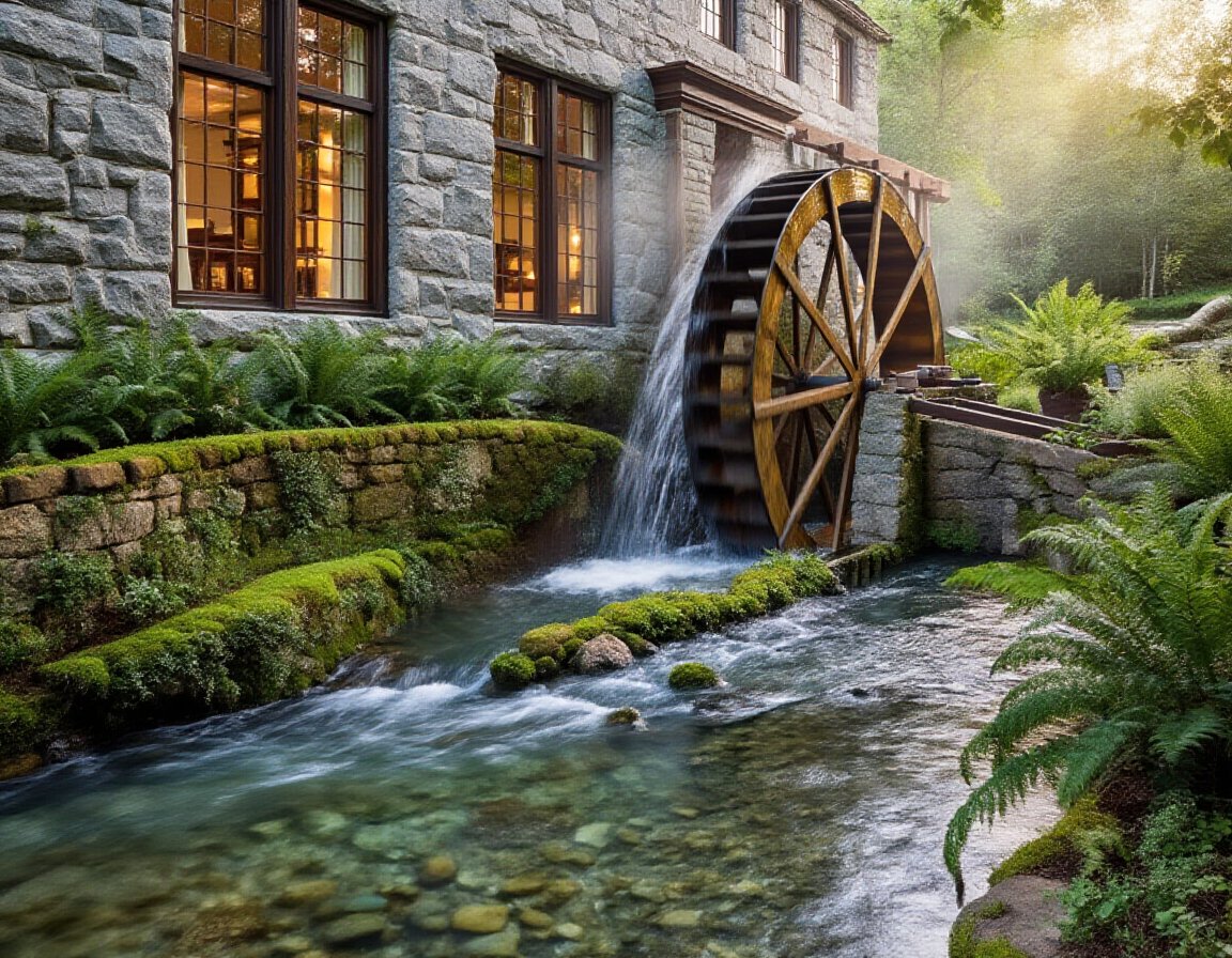
Rebuild the Wheel, Shaft, Bearings, and Gearing
Once you’ve locked the hydraulic duty point and set out the wheel-pit geometry, you can rebuild the rotating train as an engineered assembly rather than a collection of heritage parts. You’ll survey the wheel for section loss, then specify rim and bucket thicknesses, fastener patterns, and corrosion allowances; use Innovative design to hide modern stainless ties behind traditional profiles for aesthetic restoration. You’ll true the main shaft for runout, size it for combined bending and torsion, and define keyways, fillets, and surface finish to control fatigue. You’ll select bearings for radial load, thrust, and misalignment, then design pedestals with shims and jacking screws for alignment. You’ll recut gears with correct module, face width, backlash, and lubrication paths to reduce noise and wear.
Repair the Race, Sluice Gates, and Dam Safely
Although the wheel and drivetrain draw the attention, you’ll only keep them productive if the race, sluice gates, and dam handle design flows without undermining or uncontrolled drawdown. Start with a headloss check and survey the race invert for settlement, voids, and toe scour. You’ll rebuild lining and joints to resist uplift and piping, then tune gate clearances for predictable discharge curves. Keep Water conservation in mind by limiting leakage and providing metered bypass where required. Reduce Environmental impact by maintaining minimum flows and avoiding sediment pulses during dewatering.
- Confirm design flood, freeboard, and spill capacity before repairs
- Install cutoffs/filters to stop seepage and fines migration
- Use trash racks sized for debris load and approach velocity limits
- Reface gates, seals, and guides; verify full travel and locking
- Stage work with cofferdams, turbidity control, and rescue access
Make Structural Timber Repairs (Engineer-Led)
After you’ve stabilized the race, gates, and dam to control flows, turn to the mill’s load path—sills, posts, girts, joists, and wheel-pit framing—because moisture cycling and biological attack often reduce section capacity long before failure becomes obvious. You’ll have an engineer map gravity and lateral loads, probe members, and quantify remaining section versus demand. Define repair limits: scarf in sound timber where decay is localized, or sister members when checks compromise bending. Specify joinery techniques that restore moment transfer—pegged scarfs, housed tenons, and strapped connections—while keeping eccentricity low. Add concealed steel only when necessary and detail isolation from wet wood. Apply timber treatment by moisture management first: drainage, capillary breaks, breathable finishes, and targeted borate where permitted. Verify with jacking, shimming, and final plumb/level survey checks.
Source Period-Correct Parts and Modern Equivalents
You start by verifying dimensions and profiles against archival research, surviving fragments, and original drawings so your replacement parts index to the mill’s established geometry. You then source period-correct materials—species-matched timber, wrought or cast iron, leather belting, and fasteners—with traceable provenance and compatible moisture and wear behavior. Where originals can’t be obtained or safely run, you spec modern equivalents (e.g., stainless shafts, polymer bushings, engineered seals) that preserve fit, load paths, and visual intent while meeting current reliability targets.
Archival Research And Drawings
Before you touch a bearing or order a single casting, build a documentary baseline from archival sources and measured drawings so every replacement part matches the mill’s original geometry, materials, and load path. Start with Historical documentation: deeds, maintenance logs, insurer surveys, and prior retrofits. Then apply Digital archiving: scan, OCR, and tag every sheet so you can trace features to dates and revisions. You’ll convert notes into dimensioned CAD, tolerance critical bores, and locate datums from surviving reference faces. Validate by field-measuring center distances, tooth counts, shaft runout, and wheel pitch diameter, then reconcile discrepancies with error budgets. Capture assembly intent, not just shapes, so your modern equivalents preserve power flow and alignment.
- Photograph joint faces with scale and raking light
- Index drawings by component, revision, and confidence level
- Create datum trees for shafts, housings, and frames
- Record fits, clearances, and allowable misalignment
- Produce annotated exploded views for reassembly
Period-Correct Material Sourcing
With your measured drawings and archival notes locked into a datum-driven CAD baseline, start matching each component to period-correct stock so geometry and load paths translate into the right metallurgy, grain structure, and wear behavior. Prioritize Historical authenticity by tracing original bills of sale, forge marks, and timber species to local mills, foundries, and salvage yards. Specify air-dried oak or elm for wheel arms, quartersawn where bending dominates, and require ring orientation that mirrors surviving members. For ironwork, call up puddled wrought or early mild steel with verified slag stringers, then match section profiles: flat straps, fish-bellied beams, and taper pins. Document provenance, moisture content, and heat lot data in your BOM so Material sourcing stays auditable and repeatable under conservation review.
Modern Substitute Components
Although the conservation brief may demand original fabric wherever feasible, you’ll inevitably hit components whose safety margins, availability, or regulatory constraints force a substitute, so treat modern equivalents as engineered stand-ins rather than generic replacements. Specify materials and interfaces so new parts carry load, shed water, and remain reversible, while preserving Vintage aesthetics. For renewable energy output, you can hide contemporary controls behind traditional housings and keep the watercourse legible.
- Use stainless fasteners with blackened heads to match wrought-iron profiles
- Replace leather bearings with polymer-lined shells sized to original journals
- Specify laminated oak wheel paddles where solid stock can’t meet grading rules
- Install a concealed magnetic pickup for RPM without drilling historic shafts
- Swap unsafe wiring for braided-cloth, modern-rated cable in metal conduit
Recommission, Operate, and Maintain Long-Term
Once you’ve finished structural repairs and installed any new generation or drive components, you should recommission the mill in a controlled sequence that proves hydraulic performance, mechanical alignment, and safety interlocks under real flow conditions. Start with dry rotation to verify bearing temperatures, endplay, and coupling concentricity, then wet-test gates, trash rack bypass, and shutdown response at incremental heads and discharges. Calibrate sensors, log vibration spectra, and lock in setpoints for overspeed, low-flow, and seal-water loss.
Operate with a written runbook: intake clearing intervals, lubrication charts, torque checks, and seasonal debris protocols. You’ll protect historical preservation by documenting reversible changes and keeping original fabric unloaded where possible. Use community engagement for volunteer inspections, interpretive tours, and rapid reporting of leaks, noise, or scouring.
Frequently Asked Questions
How Much Does It Typically Cost to Restore a Historic Water Mill?
You’ll typically spend $250,000–$2,000,000 to restore a historic water mill, depending on Historical preservation requirements, Structural integrity repairs, dam and raceway rehab, turbine replacement, permitting, environmental mitigation, and specialty millwright labor.
How Long Does a Full Mill Restoration Project Usually Take?
You’ll usually need 12–36 months; the “fast-tracked” theory often fails because hidden rot and hydraulics dictate sequencing. You’ll integrate modern machinery with preservation techniques, coordinate permits, structural stabilization, wheel rebuilds, and commissioning.
Can the Mill Be Insured During and After Restoration Work?
Yes, you can insure it during and after work. You’ll need builder’s risk and specialized Insurance policies, guided by formal Risk assessments. You should document materials, phased scopes, flood/fire exposures, and post-restoration operational coverage.
What Grants or Tax Incentives Are Available for Heritage Mill Restoration?
You can pursue heritage preservation grants, state historic rehabilitation tax credits, and federal credits if you qualify. You’ll need a rigorous grant application: documented significance, conservation-grade specs, phased budgets, compliance reviews, and matching-funds commitments.
How Can Restored Mills Generate Income Through Tourism or Education?
You’ll generate income by offering paid tours, workshops, and field labs. Example: you’ll run a weekend milling demo with ticketing, a small exhibit, and a classroom. Prioritize Heritage preservation, embed Community involvement, and streamline visitor circulation.
Conclusion
You bring a historic water mill back into productive use by locking down its purpose, then validating water yield, access, and compliance constraints. You document the original layout, survey structure and drivetrain condition, and verify head and seasonal flow with measured data. You repair races, sluices, and dam works to modern safety factors, then execute engineer-led timber stabilization and component replacements. When you commission under defined operating protocols, remember: measure twice, cut once.